Two weeks ago, I partook in a hackathon revolving around Fast Healthcare Interoperability Resources (FHIR) — a standard defining the format of electronic health records. This experience was an eye-opener, a true deep-dive below the surface to the rest of the iceberg that is healthcare data. Using FHIR, teams were challenged to address particular problems in any way they pleased — as long as it leveraged integration to FHIR systems.
Our team spent the majority of the time playing around with the data — it was not until the last few hours that we addressed the problem and built a cute little vitals baseline dashboard. It was something clean, simple, and illustrated only what we wanted to — patient vitals and vital correlations.
We did not win unfortunately. There were a plethora of other really neat FHIR projects, leveraging all sorts of tech from machine learning frameworks to AI-powered parsers.
Either way, we packaged up our project and archived it away for later to fiddle with.
It was during a git commit that I began to wonder when I’ll be seeing this code again. How many projects reach the end-of-the-line? How many projects never seek fruition?
Not long from now we will be seeing a surge of new interns enter the tech space for winter 2022, along with a surge of fresh hires starting their IT journeys.
If you have reached this far, congratulations! You have already convinced your employer of your unique talents that make you best suited for this role. Keep that ball rolling and show the rest of your team why you belong there as well!
Make a strong first impression, arrive early, and submit deliverables on time — all of which are generic advice heard at the beginning of employment. Let us skip the boring-alities and head straight to some of the meat and gravy that will make you highly successful, fast.
At the core of it, both leadership and your team members are looking for integration. How well do you fit in on a daily basis? Can you work together with the team on similar problems while bringing your own creativity to the table? If you got up and left tomorrow, will the team even notice? Your worth on any team must be visible — highly specialized/siloed initiatives do not count.
For this piece, we will dive into what some of the technical pieces you can embark on to reach new levels of involvement that will build a strong foundation to help you integrate with your team, and the overall organization.
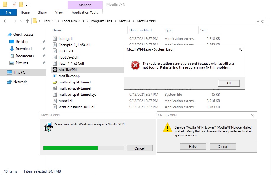
Encountered this issue during the install process of Mozilla VPN’s Windows 10 client to a Windows Server 2019 virtual host.
During install, the Mozilla VPN MSI threw the following error:
Service 'Mozilla VPN (broker)' (MozillaVPNBroker) failed to start. Verify that you have sufficient privileges to start system services.
This looks like a post-installation step, since all necessary binaries are already located in C:\Program Files\Mozilla\Mozilla VPN
Running C:\Program Files\Mozilla\Mozilla VPN\MozillaVPN.exe resulted in the following error, which immediately hinted at the issue:
The code execution cannot proceed because wlanapi.dll was not found. Reinstalling the program may fix this problem.
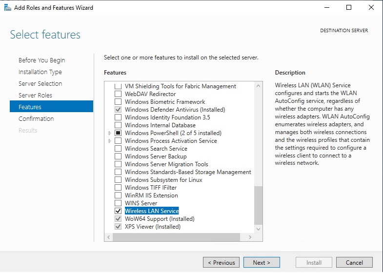
I’m installing this client in a Windows Server 2019 VMware VM, which does not have a wireless NIC. It does not look like Wireless LAN Service was installed either.
After installing the service through Server Manager’s “Add Roles and Features Wizard” (note this will require a restart), I can successfully complete installation, and start the Mozilla VPN service.
To resolve, install Wireless LAN Service windows feature
Four score and several nights later, TOConnect 2021 comes to an end. As for participants, their journey has just begun - whether that’s continuing education, entering the workforce, or starting a new project of their own.
Nonetheless, the TOHacks team is proud to have been a part of it by imparting knowledge and valuable skills through various mastermind workshops from data science and machine learning to demystified tech and tech diversity. We also held project management and personal branding workshops, fueling the entrepreneur within.
At TOHacks, we take learning — and corgis — seriously. As such, believe us when we say it: the rough plunge into virtual-everything does not need to stunt your learning.
Muster the courage, whip out your digital notepad and connect with us @ TOConnect 2021 — a 4-week accelerator designed to help you build out your next BIG idea.
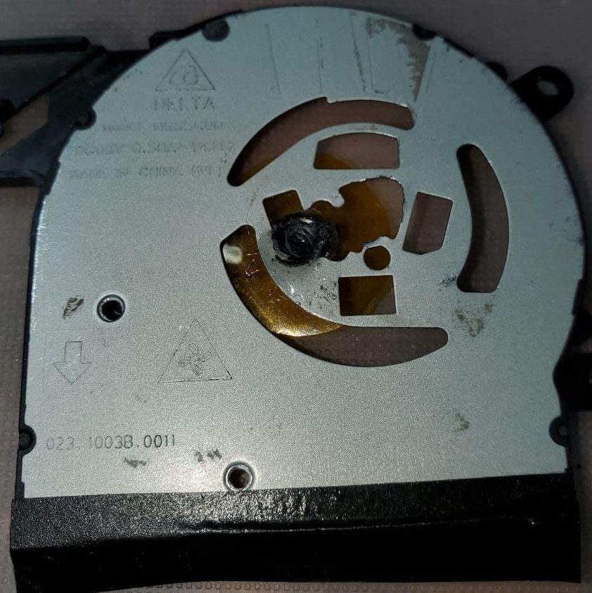
A good friend of mine recently had their HP Envy x360 fan die on them – which kind of sucks since the system won’t actually boot past the post screen warning of fan malfunction. Cause looks to be burn-out – a combination of heavy dust and an impact on the bottom led to a jam.
Thankfully HP provides spares, and goes through the effort of labeling everything with an ‘HP Spare’ part label.
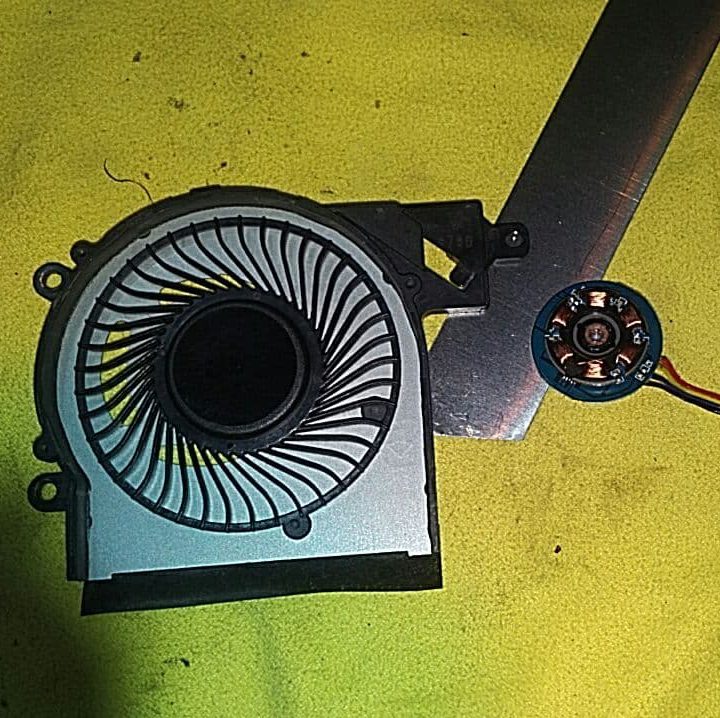
Now here’s the kicker – the lad goes out and gets the wrong fan. Not just the wrong enclosure, but wrong dimension and connector as well.
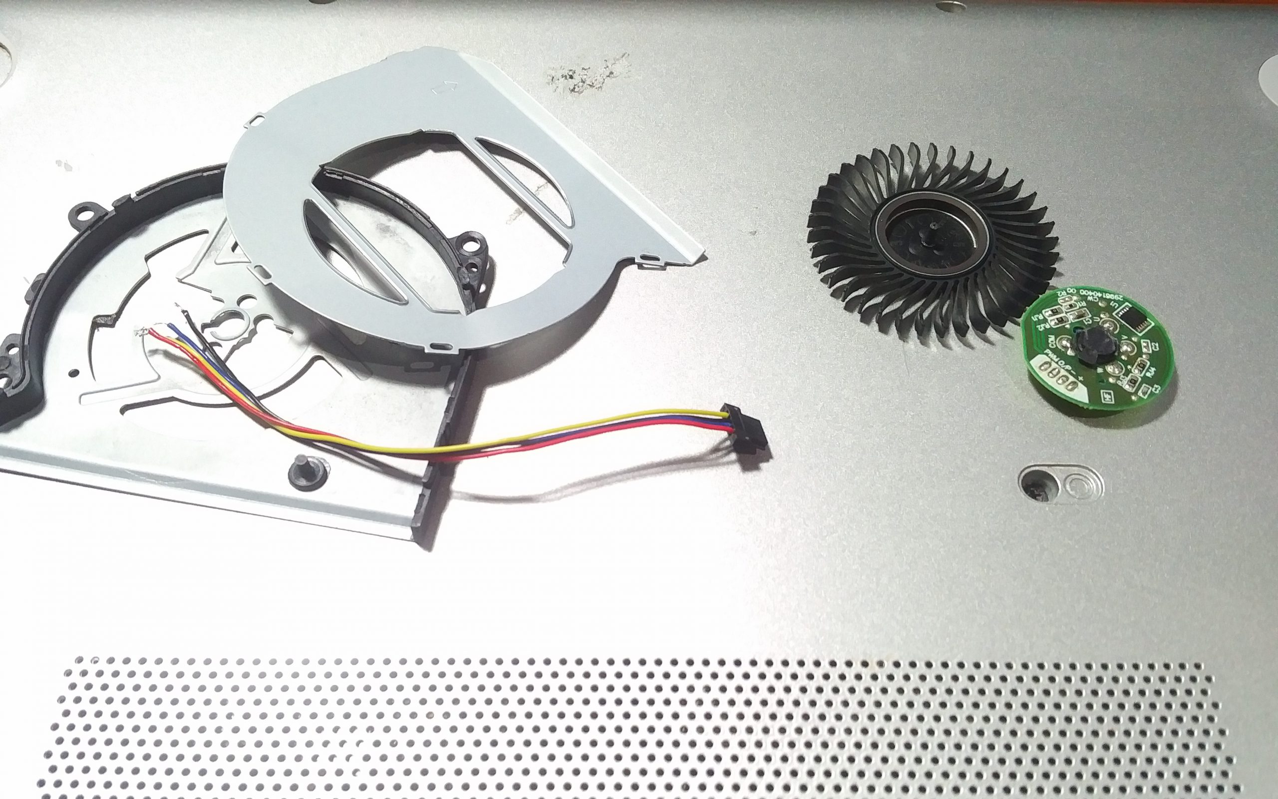
New, mysterious fan that I can’t recognize on the left, and the original dead HP Envy x360 fan on the right
Normally this is the point where most technicians would acknowledge the part incompatibility and purchase a new one, but we were both feeling a little… experimental.
And that’s where this story begins – a tale of how I Frankenstein together a completely illegitimate HP Spare 809825-001 laptop fan.
What are we working with?
The only commonality between the two fans is that they’re 5V 0.5A, brush-less. While both are 4-pin, they’re wired differently and with a different connector. Form factor of their enclosures is very different, no room here for negotiation. In addition, the propeller for the new fan is significantly larger than the old one.
All in all, my goals are to swap all the components from the new fan (minus the housing and connector cable), with the old fan.
Key things I’ll need to keep track of are:
Old fan tear-down
Neat tear-down of the old fan, since we’ll be re-using its housing
De-soldering of the old fan’s 4-wire cable
New fan tear-down
Neat tear-down of the new fan, don’t want to damage the motor
De-soldering of the new fan’s 4-wire cable
Fan-kenstein
Soldering of the old 4-wire cable to new brush-less fan motor
Securing new brush-less motor in old fan housing
Accommodating new fan propeller dimension in old fan housing
Re-assembly
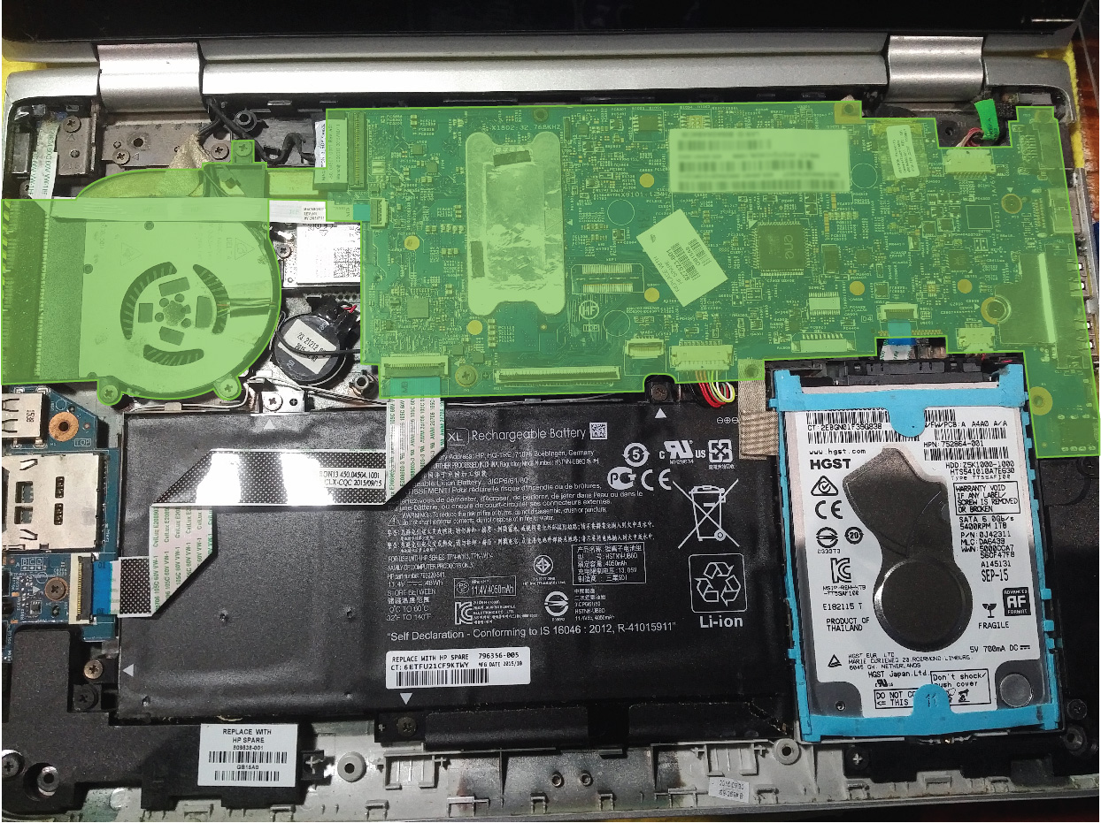
Lay of the land
Green area is all one assembly including the motherboard, heat pipe, and fan assembly
First step is to get at just the fan assembly. To do so I had to remove the top keyboard assembly covering the system above, then remove the green highlighted assembly altogether. The fan is held onto the heat pipe with a plastic clip, and black tape serving as a dust shield.
Tear-downs
Extracting parts from both fan assemblies wasn’t too bad. The new one used plastic rivets which were destroyed in the disassembly but don’t matter since we only care about re-using the old assembly.
The column where the propeller spindle rests in was press-fit into both assemblies. Heating that area with a heat gun helped soften the plastic enough so that I could push the motor assembly out of the housing.
Fan propellers above each fan housing, old fan on the left, new fan on the right
First impressions of both open assemblies – I’ll either have to mount the new motor in the same location and cut the fan smaller, or move the mount to the center of the housing, and dremel that.
Either way, both motors were removed from their respective housings and their wiring swapped.
Motor and fan blade we’ll be using. Playing around with the positioning of the fan blade.
De-soldering wire from old fan motor. We’ll be re-using it on the new fan since the connector differs.
Fan-kenstein
The one thing they never tell you about these laptop fan assemblies… the motors are press-fitted.
Actually, let’s be more specific. Looking at the above figures, we can see the rear of each motor unit and a plastic extrusion. That extrusion is press-fitted in a particular contour of its housing. The fan propeller’s spindle fits into here, with this piece sitting in the center of the motor.
To secure the new fan assembly in the old housing, I had to dremel a hole in the housing, along with stand-offs which would hit the fan propeller. Holding this piece is strong epoxy. The motor would then rest on the yellow plastic circle.
Rear of old fan housing with new motor centered in dremelled area. Holding it in place is an epoxy solution.
Flipped rear of old fan housing with new motor centered in dremelled area. Holding it in place is an epoxy solution.
Centering and securing the motor assembly wasn’t bad, and once secured, the fan propeller fits without issue. At this point we’ve got something just like this. All that’s left is to secure this housing to its other half. That other half just so happens to be a part of the heat pipe assembly. A part which does not fit the new clearance required for the fan propeller.
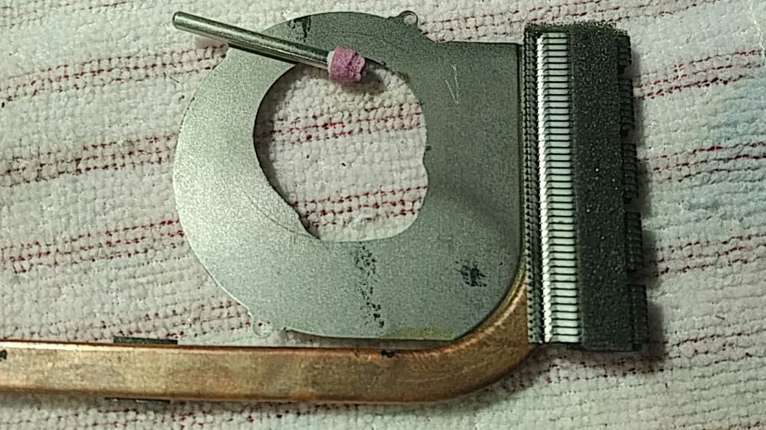
Yes, we whip out the dremel once more. I found it helped to sharpie out the area I need to clear, that way I’m not removing excess.
Fan plate, which is one with the heat pipe assembly, also dremelled to make clearance for the new fan propeller.
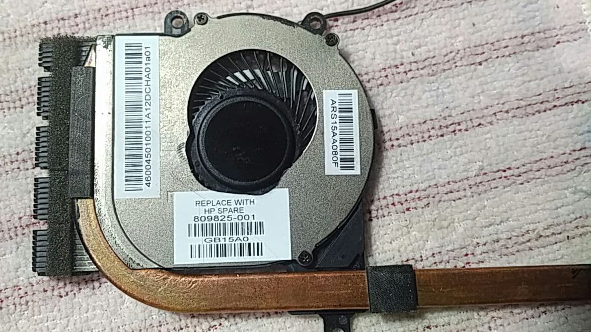
Once dremelled, the rest of the heat pipe and fan re-assembly went well. Reattachment was done with just 3 screws. I made sure to check for free fan movement before completing re-assembly of the machine.
Final reassembled fan unit using new motor and fan propeller in old housing.
Reflection
And there we go, that concludes the story of how we made an illegitimate HP Spare fan for the HP Envy x360 using a fan that definitely did not belong in this laptop.
A few things that if done again (which if I do, know I’m being held against my will):
Find a more secure and long-lasting way to hold the motor to the housing. The epoxy solution I used was pretty strong, and the unit should be protected from impact thanks to the rear laptop cover, but if it ever takes a direct hit I fear it can dislodge the epoxy.
Use a smaller fan, or cut the propeller down. There wasn’t much clearance left in the housing for airflow/dust.
Use the proper dremel tool. Grinding heads aren’t made for removing that much material, and mine really wore out.
Remaining parts from the new fan unit (left) and old fan unit (right)
Introducing Scarborough Repair and Bike Cafe’s series of virtual repair and bike safety/mapping workshops via zoom. These workshops aim to encourage a culture of reducing waste and promoting sustainability.
Neat little virtual event being organized by the Woburn Scarborough Community.
I’ll be there talking about PC Hardware & Software, namely common failure mechanisms and how to prevent, anticipate and react to them.
A majority of the gaming I’ve done throughout the years has been on the PC – keyboard & mouse are a lot more in my comfort zone, not to mention the plethora of titles available. Despite this, if I was to choose a favourite console, it would have to be the Nintendo Switch. It’s a highly versatile piece of hardware, capable of mobile or docked game-play on a larger screen while maintaining a decent battery life, touchscreen, and detachable controllers. Not to mention the internal system specs, which are pretty hardcore considering the package size:
CPU/GPU
Custom NVIDIA Tegra (X1-based)
Storage
32 GB Internal, supports microSD up to 2TB
Wireless
Wi-Fi (IEEE 802.11 a/b/g/n/ac) Bluetooth 4.1
Video
1080p when docked, 720p on built-in 6.2-inch LCD Screen / 1280 x 720
The only drawback is that it’s, well, a console. Like all consoles, access to the underlying system is greatly restricted in the favor of a ‘just works’ system – meaning no custom software, and definitely no hardware mods. The Nintendo Switch in this case operates on Horizon OS, closed-source software with pieces from FreeBSD and Android. Either way, it’s a shame considering the computing power packed into such an elegant, mobile package. Imagine its potential in areas such as robotics and automation where the system can operate as a control panel!
Definitely lots of potential here, and thanks to the hacker/homebrew community, steps are taken every day to unlock more of the system’s true potential – the most daunting and groundbreaking of these was exploiting the system in recovery mode (RCM) to be able to inject custom payloads via the Fusée Gelée coldboot vulnerability. This permits arbitrary code execution – effectively allowing us to run custom code in the active stack while the system remains powered on. Enter left-stage, homebrew.
Here’s to a contribution that should hopefully get more feet off the ground – let’s look into how we can build into the Switch’s natural system a safe way to enter RCM.
Requirements
Nintendo Switch System
While we can enter RCM on a patched Nintendo Switch system, it’ll probably be less useful from a homebrew perspective since Fusée Gelée is patched. You can check if your system is patched by validating its serial # against known lists containing device models created before/after the patch, or by entering RCM and trying to inject a payload. Both of these are covered over at switch.homebrew.guide.
Tools & Equipment
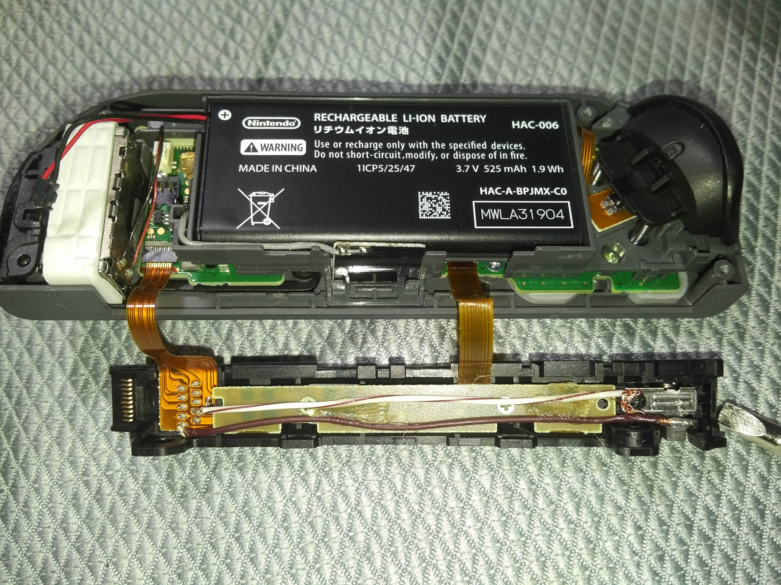
If it wasn’t clear, this is a hardware modification to your Nintendo Switch system – specifically the RIGHT JOYCON. This exploit leverages the right Joycon rail by adding a switchable short to two pins in the Joycon, which when combined with power and volume UP trigger RCM on boot. Stuff we’ll need to get this going include:
Y0/Y1 (tri-wing) Screwdriver
PH0/PH1 (phillips) Screwdriver
24 AWG or thinner insulated wire (single-strand preferred)
Wire stripper
Fine-tip soldering iron and solder
Epoxy
Toothpick (for applying Epoxy)
Hot glue
We’ll be working in tight delicate quarters so an overhead lamp along with helping hands to secure components would be great. Otherwise, some tape and wooden blocks to hold parts in place will suffice.
In the end we’ll use a multi-meter on continuity mode to test our work.
Time & Skill
We’ll be soldering in areas with ~1mm distance from other joints, so steady hands and patience are going to be key to reduce chances of damaging the right Joycon. With all of the above equipment and sufficient skill, estimated time to completion is 30 minutes to 60 if you’re new to this.
Procedure
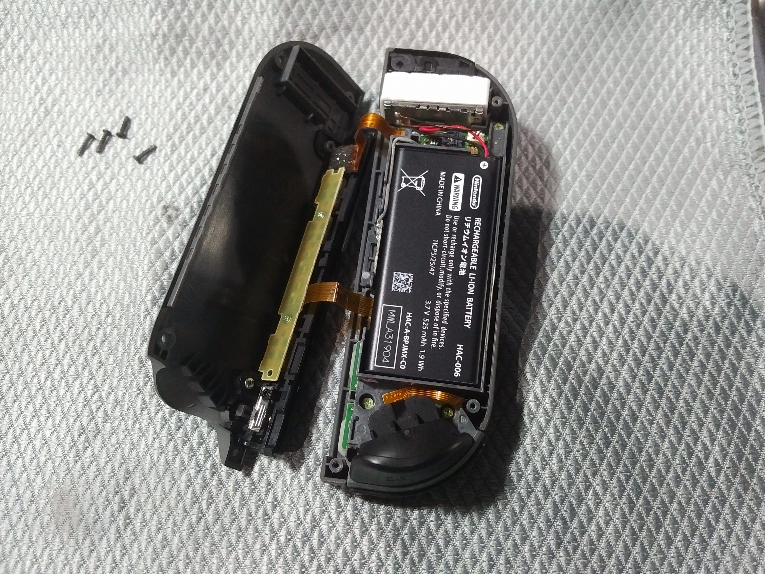
Step 1. Open the right Joycon by removing the 4 tri-wing screws
The rear cover will lift off, leaving the majority of components in the front cover. Pry the two off gently – there are two ribbon cables running from the rail attached to the rear cover and the PCB in the front cover.
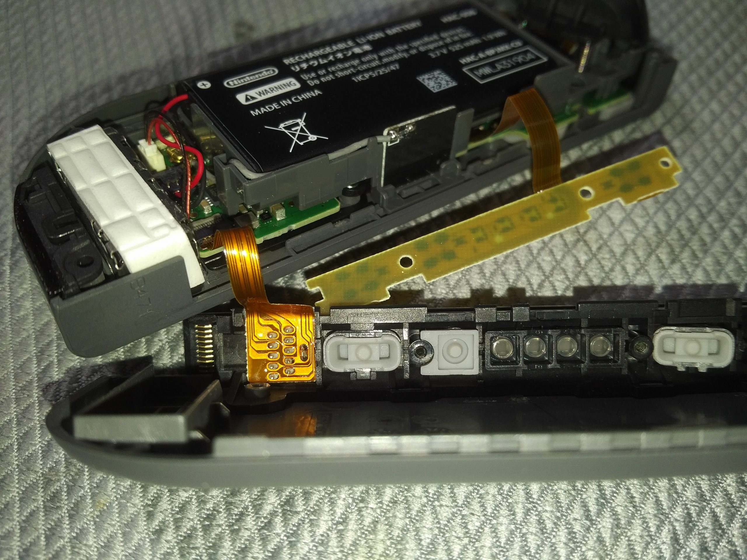
Step 2. Unscrew the LED PCB and remove protective padding for Joycon rail pins
To give us more room to work, unscrew the two silver Phillips screws holding the LED PCB in place. That’s one ribbon cable we can move aside now. Note that this piece holds the rail buttons (SR, SL, Bluetooth Sync). Remove all 3 of these buttons and put them aside should they fall out of the rail and go missing while we’re working.
To reveal our actual work surface, carefully remove the grey foam pad and put it aside – we’ll be reapplying this in the end. We now have access to the pins we’ll be soldering to.
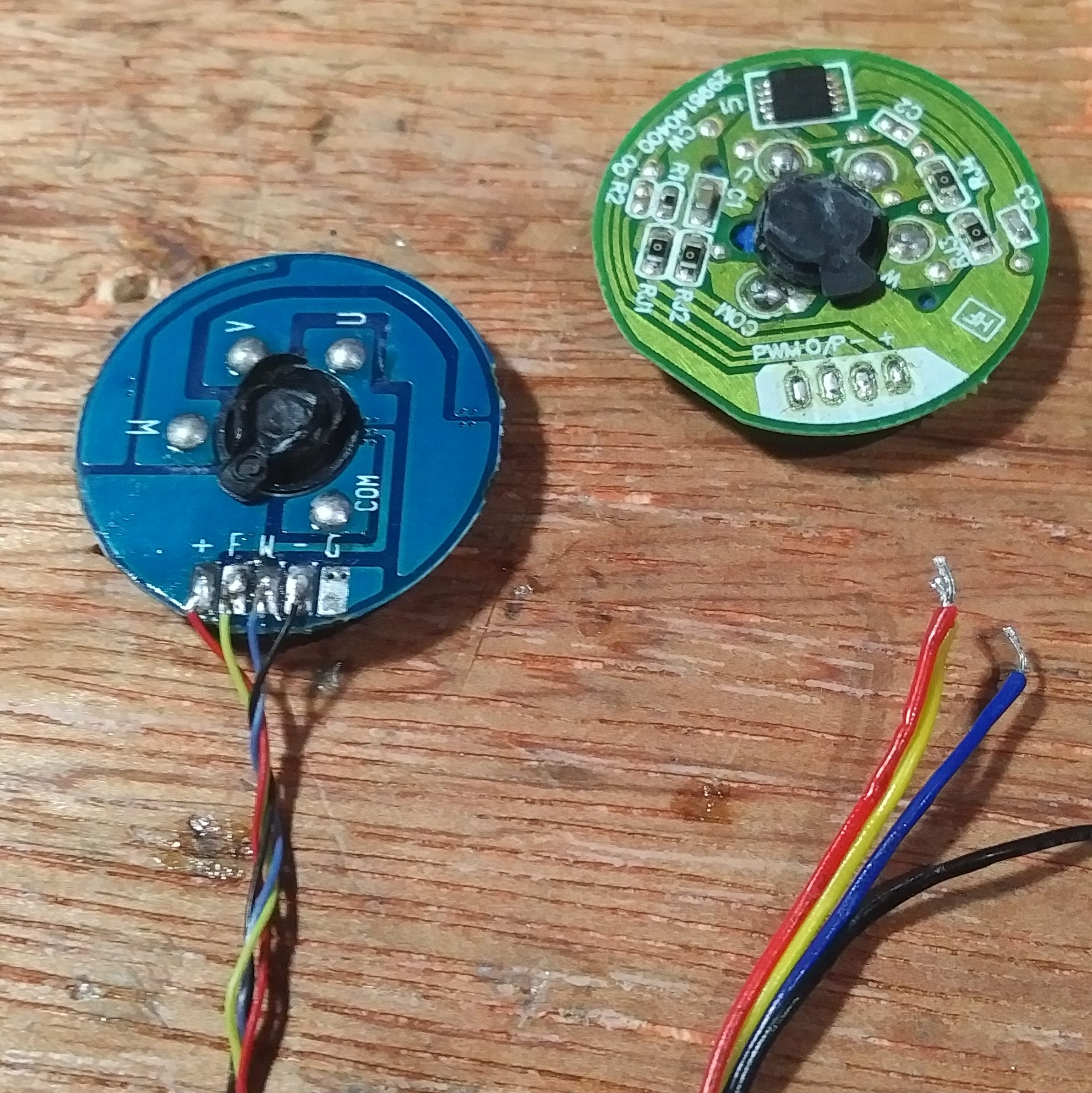
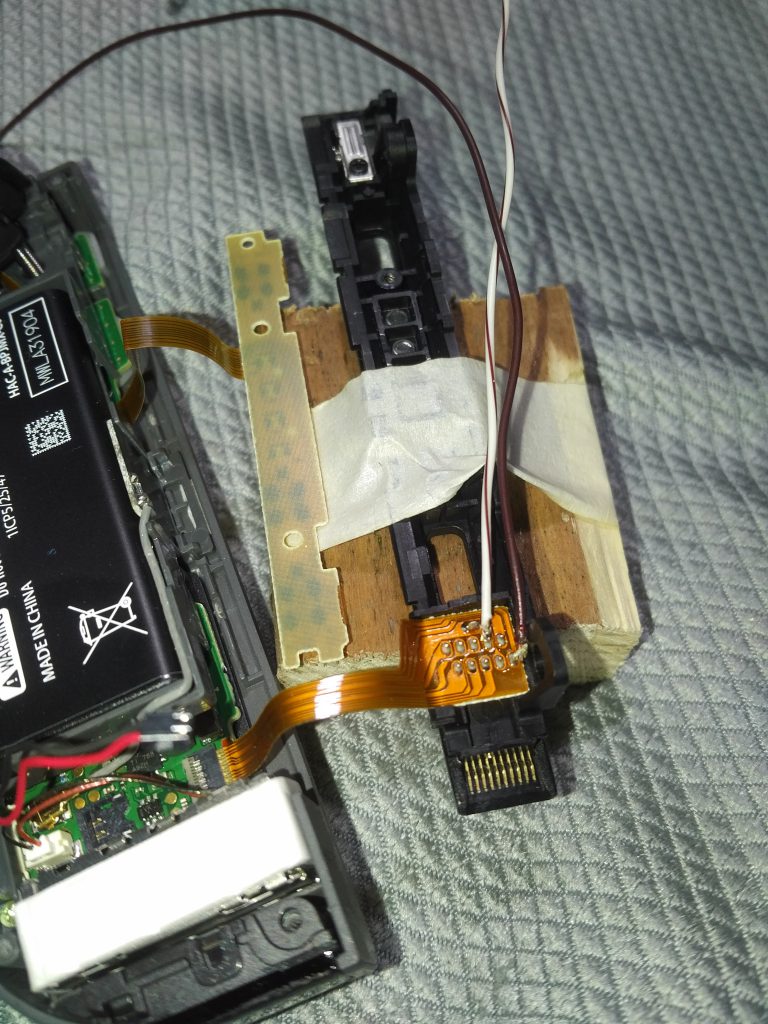
Step 3. Solder 10 cm (4 1/2″) lengths of wire to pins 7 and 10
Cut two 10 cm (4 1/2″) lengths of thin wire. Strip 1mm (1/32″) off one end of both (or melt it with your soldering iron). We will be soldering 1 wire to Pin #7, and the other to Pin #10. Both lengths will be running along the rail heading towards SR. We’ll trim excess later.
Right Joycon rail internal pin-out
Some strategies for this solder job:
Apply a small blob (no more than 1mm (1/32″) in size) to the tip of your iron.
Apply this solder to just your wire.
Place the wire against the pin, and heat the joint with a clean tip.
This will result in a complete joint from both solder melting and joining. I noticed this works great with multi-strand wire as it keeps it together long enough to complete the solder. Here’s my make-shift setup on a block of wood.
Step 4. Re-assemble LED PCB to rear cover rail, and hot glue both wires to the back of it
Replace the SR, SL, and Bluetooth sync buttons (make sure not to mix them up), and screw back in the LED PCB. Hot glue the two strands of wire to the back of this PCB running along the length towards SR.
Make sure to flatten your hot glue blobs, otherwise you’ll have difficulty in reassembly of the Joycon. These blobs help us secure the wires for the next operation – building our switch.
(graphic in last step)
Step 5. Strip 1cm (1/2″) of Pin #7 wire from the black release switch screw – strip and trim the rest off then wrap the stripped end around the black screw
To make this switchable, we’ll leverage the Joycon release button and make it electronically functional. The 1cm (1/2″) of stripped wire extending past the black screw is to be wrapped tightly around it (helps to unscrew it slightly first). The screw and silver piece of metal are conductive, and will serve as the static part of our switch.
(graphic in last step)
Step 6. Measure wire from Pin #10 to the end of the gray Joycon release wire – trim the rest off, strip 2mm (1/16″), and solder a flat blob no thicker than 1mm (1/32″) to the end
Measure the remaining Pin #10 length all the way to the gray Joycon release lever and cut off the excess. Strip 2mm (1/16″) of wire off this end for some solder. We’ll be making a 5mm (3/16″) wide circle, 1mm (1/32″) thick of solder at the end. Solder’s pretty soft, so you can get away with adding the solder, then flattening with a plyers.
Step 7. Secure solder pad to face of Joycon release lever moving inwards using epoxy
Attach this solder pad to the face of the lever actuating inwards (the lever moves in/out of the Joycon) using epoxy. Care should be taken that epoxy does not leak (hence, use a toothpick to apply), and is ONLY contacting the surface of the lever moving inwards, and not the arm of the lever moving behind the small silver metal plate.
When the lever is fully actuated (pressed inwards), the solder pad should contact the edge of the metal plate, completing our switch circuit and creating a short between pins #7 and #10. You’ve just built a de-facto normally-open (NO) switch!
Step 8. Test our NO switch – touch multi-meter probes to pins #7 and #10 while lifting and releasing the Joycon release switch lever
If your continuity test results in continuity when our lever is pressed inwards, and none when released, then our NO switch is complete and functional.
Step 9. Replace padding protecting rail pins, then reassemble Joycon
At this point we’re done modifying our right Joycon. We can begin reassembly by placing our little gray piece of foam back over the rail pins, trim any exposed wire and flatten connections/hot glue to keep the entire unit compact. Due to the gauge of chosen wire, your reassembly may be a little tough. Squeeze the two halves together like a sandwich, and use a rubber-band if needed to keep the unit together long enough to screw back in the back cover.
Complete RCM Right Joycon Rail modification
How to use
Whenever you have a Nintendo Switch unit that needs to enter RCM, attach the right Joycon to the unit, and power the unit down.
Hold the RIGHT JOYCON release button, Volume UP, and Power at the same time for 1 second, then release.
If nothing happens visually, then your switch is in RCM mode, and you can proceed with injecting whatever fun payloads you have in mind over USB-C 🙂
Next steps and thanks
Big thanks to the following communities and projects for making this possible.
The short answer – a hell of a lot more than the typical consumer has available to them in terms of finances, skills, and time. Considering the typical repair, a modern laptop that may need a screen replacement can easily expect replacements to be in the $100 CAD range. This isn’t including tool costs needed to deconstruct overtly complex enclosures with torx and tri-wing screws, all the while exercising surgeon-level patience and skill.
Criticizing CBC in the comments? Sure. Criticizing the tech and the repairs? Come on, now I’m a little hurt.
CBC does an okay job at bringing to light that there’s an issue, but doesn’t quite elaborate on it in detail, something I wish they would’ve done. Guessing they did so to adhere to as much of the general public as possible? Eh, who knows.
Either way, my hope was that everyone took away 1 thing at minimum – that repairability of electronics has gone down the drain. Instead, I scroll down and find that some of the most popular comments are those criticizing the evidence, the repair, the expectations:
“10 years for a laptop is pretty good… I’d be satisfied”
“‘They almost feel like make the battery not to last’ That’s how lithium ion battery works”
“How do you expect for an phone or any technology to last forever?”
Well damn, when did we start accepting that garbage endurance/durability were the price of innovation? I cannot fathom the individuals who would use this mindset in other fields of science. Today, the lifespan of humans has grown tremendously from what it was decades ago thanks to the same mindset shared by my team – we need to be better than we were. No exceptions.
Those who are okay with devices and components having significantly less lifespan than their predecessors, those who are okay with being unable to repair their device as long as it is future-tech, you need to check yourselves. This is toxic mentality that goes against progress, and your normalization is letting the big players know that it’s okay to get away with this nonsense.
Our family owns and regularly uses a blender about as old as I am. I’m afraid the day this thing kicks the bucket and I can no longer repair it, it’ll be disposable blenders from there on out.
Now here’s something I wished more people talked about. For the uninformed, Bill 72 is an amendment to the consumer protection act in Ontario. It requires a company to give a consumer or repair shop what they need to repair the electronic products themselves. The company can charge for this, but within limits.
Some key takeaways from this include:
Upon request, companies NEED to provide most recent versions of documents (for free if digital), replacement parts, software, and other tools needed to diagnose, maintain, and repair.
Replacement part costs must be fair, and should not be used for prime profit gain.
Now this is the good stuff. We’re talking some major quality-of-life improvements for electronics owners!
Able to extend the longevity of your own electronics, by yourself. This builds brand loyalty and trust – something severely lacking in the modern market.
Ability to learn more about your electronics. I’m a big sucker for learning new things, and this is a great way to exercise a lot of the theory we learn in school on practical systems. Furthermore, ethical white-hat hacking of these systems today can bring about improvements tomorrow.
Less environmental impact from more sustainable systems. The more devices we can repair ourselves, the less end up in landfills. Simple math, and anyone that feels the need to fact-check this is an idiot.
Better adherence to industry standards. Repairability of devices involves modular design. This helps product holders both adhere and contribute to standards.
Now these are just a few benefits. There are so many more if you give it a quick search and/or observe it yourself from various grassroots such as ourselves, Fixit Clinic, IFixit, and more.
There’s not to say there aren’t any cons – the major one being concerns about intellectual rights violations. But really, these pros outweigh those cons you selfish bastards, you should think twice if your product loses its integrity the moment the lid comes off.
Closing
To round out the narrative, why were only 2 of the dozen or so devices we saw that day repaired successfully? A lot of our repair setups were improvised the day-of, replacements weren’t available, we had 30 minutes per device (take was done in 1 afternoon), not to mention that some of these were plain irreparable (severe water damage, physical trauma, etc).
It’s really unfortunate that CBC didn’t show this stuff, because they should’ve had it all recorded – a majority of our interactions as fixers were very descriptive and informative. That’s just how we work – we’re not some 3rd party repair shop, we’re skilled volunteers contributing back to the community, teaching others how we’re doing things, why it’s that way, all while learning more ourselves.
To summarize, repairability is pretty neat, thanks CBC, and looking forward to doing more of this in the open once COVID-19 settles down.