
A majority of the gaming I’ve done throughout the years has been on the PC – keyboard & mouse are a lot more in my comfort zone, not to mention the plethora of titles available. Despite this, if I was to choose a favourite console, it would have to be the Nintendo Switch. It’s a highly versatile piece of hardware, capable of mobile or docked game-play on a larger screen while maintaining a decent battery life, touchscreen, and detachable controllers. Not to mention the internal system specs, which are pretty hardcore considering the package size:
| CPU/GPU | Custom NVIDIA Tegra (X1-based) |
| Storage | 32 GB Internal, supports microSD up to 2TB |
| Wireless | Wi-Fi (IEEE 802.11 a/b/g/n/ac) Bluetooth 4.1 |
| Video | 1080p when docked, 720p on built-in 6.2-inch LCD Screen / 1280 x 720 |
| Audio | Stereo, supports 5.1ch PCM output |
| Battery | 4310mAh |
| Sensors | Accelerometer, gyroscope, and brightness sensor |
The only drawback is that it’s, well, a console. Like all consoles, access to the underlying system is greatly restricted in the favor of a ‘just works’ system – meaning no custom software, and definitely no hardware mods. The Nintendo Switch in this case operates on Horizon OS, closed-source software with pieces from FreeBSD and Android.
Either way, it’s a shame considering the computing power packed into such an elegant, mobile package. Imagine its potential in areas such as robotics and automation where the system can operate as a control panel!
Definitely lots of potential here, and thanks to the hacker/homebrew community, steps are taken every day to unlock more of the system’s true potential – the most daunting and groundbreaking of these was exploiting the system in recovery mode (RCM) to be able to inject custom payloads via the Fusée Gelée coldboot vulnerability. This permits arbitrary code execution – effectively allowing us to run custom code in the active stack while the system remains powered on. Enter left-stage, homebrew.
Here’s to a contribution that should hopefully get more feet off the ground – let’s look into how we can build into the Switch’s natural system a safe way to enter RCM.
Requirements
Nintendo Switch System
While we can enter RCM on a patched Nintendo Switch system, it’ll probably be less useful from a homebrew perspective since Fusée Gelée is patched. You can check if your system is patched by validating its serial # against known lists containing device models created before/after the patch, or by entering RCM and trying to inject a payload. Both of these are covered over at switch.homebrew.guide.
Tools & Equipment
If it wasn’t clear, this is a hardware modification to your Nintendo Switch system – specifically the RIGHT JOYCON. This exploit leverages the right Joycon rail by adding a switchable short to two pins in the Joycon, which when combined with power and volume UP trigger RCM on boot. Stuff we’ll need to get this going include:
- Y0/Y1 (tri-wing) Screwdriver
- PH0/PH1 (phillips) Screwdriver
- 24 AWG or thinner insulated wire (single-strand preferred)
- Wire stripper
- Fine-tip soldering iron and solder
- Epoxy
- Toothpick (for applying Epoxy)
- Hot glue
We’ll be working in tight delicate quarters so an overhead lamp along with helping hands to secure components would be great. Otherwise, some tape and wooden blocks to hold parts in place will suffice.
In the end we’ll use a multi-meter on continuity mode to test our work.
Time & Skill
We’ll be soldering in areas with ~1mm distance from other joints, so steady hands and patience are going to be key to reduce chances of damaging the right Joycon. With all of the above equipment and sufficient skill, estimated time to completion is 30 minutes to 60 if you’re new to this.
Procedure
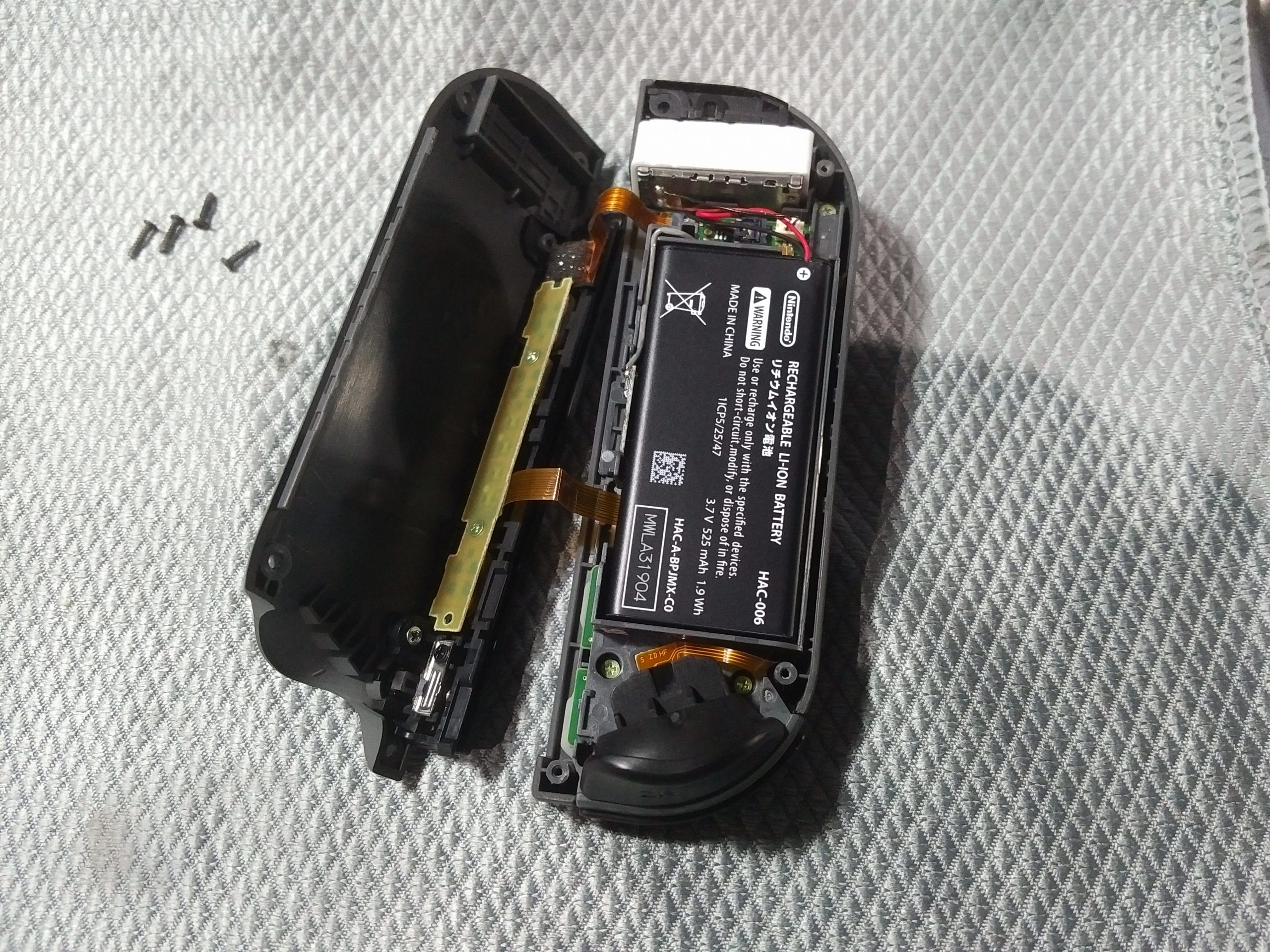
Step 1. Open the right Joycon by removing the 4 tri-wing screws
The rear cover will lift off, leaving the majority of components in the front cover. Pry the two off gently – there are two ribbon cables running from the rail attached to the rear cover and the PCB in the front cover.
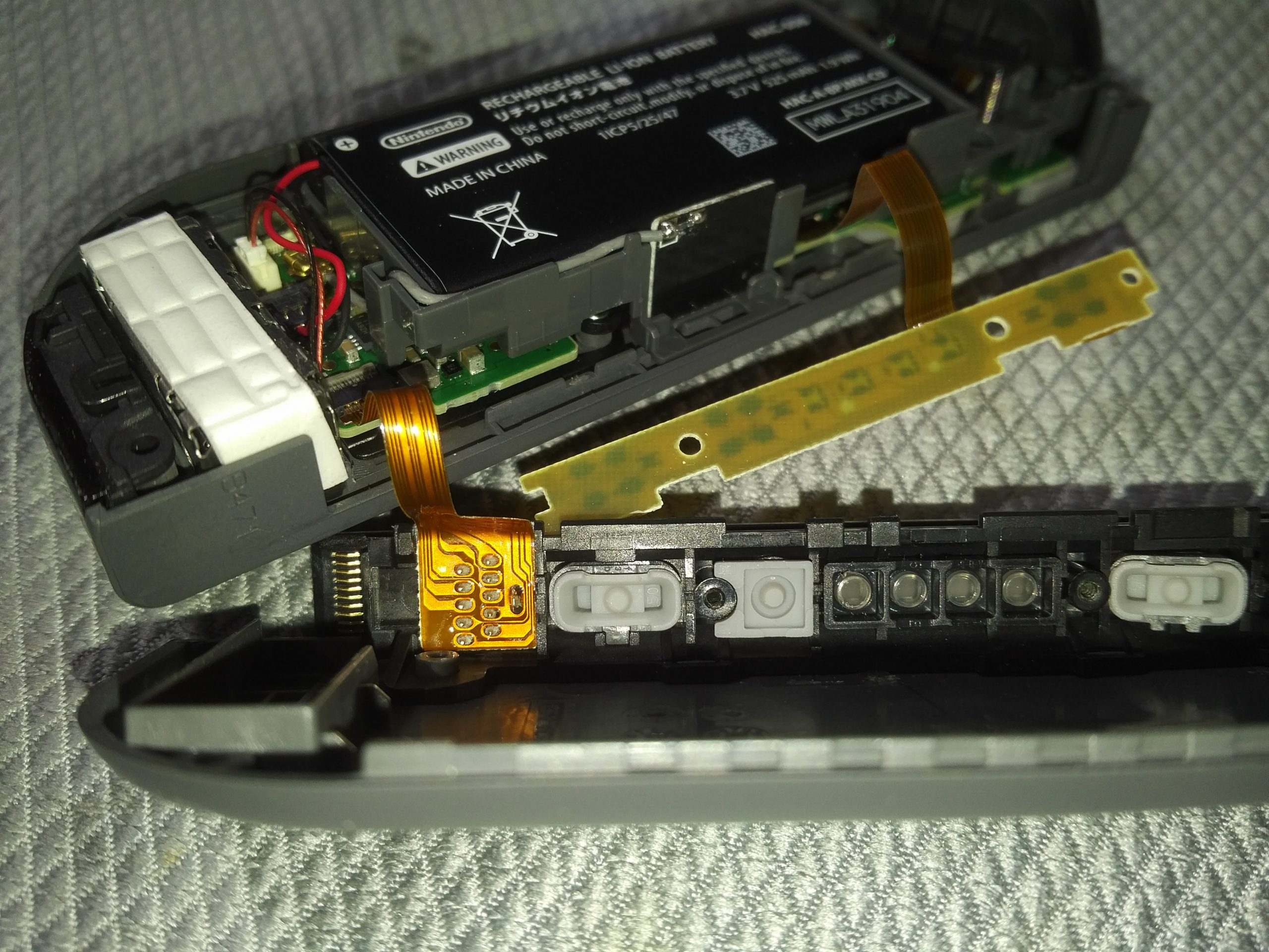
Step 2. Unscrew the LED PCB and remove protective padding for Joycon rail pins
To give us more room to work, unscrew the two silver Phillips screws holding the LED PCB in place. That’s one ribbon cable we can move aside now. Note that this piece holds the rail buttons (SR, SL, Bluetooth Sync). Remove all 3 of these buttons and put them aside should they fall out of the rail and go missing while we’re working.
To reveal our actual work surface, carefully remove the grey foam pad and put it aside – we’ll be reapplying this in the end. We now have access to the pins we’ll be soldering to.
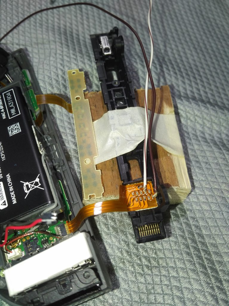
Step 3. Solder 10 cm (4 1/2″) lengths of wire to pins 7 and 10
Cut two 10 cm (4 1/2″) lengths of thin wire. Strip 1mm (1/32″) off one end of both (or melt it with your soldering iron). We will be soldering 1 wire to Pin #7, and the other to Pin #10. Both lengths will be running along the rail heading towards SR. We’ll trim excess later.

Some strategies for this solder job:
- Apply a small blob (no more than 1mm (1/32″) in size) to the tip of your iron.
- Apply this solder to just your wire.
- Place the wire against the pin, and heat the joint with a clean tip.
This will result in a complete joint from both solder melting and joining.
I noticed this works great with multi-strand wire as it keeps it together long enough to complete the solder. Here’s my make-shift setup on a block of wood.
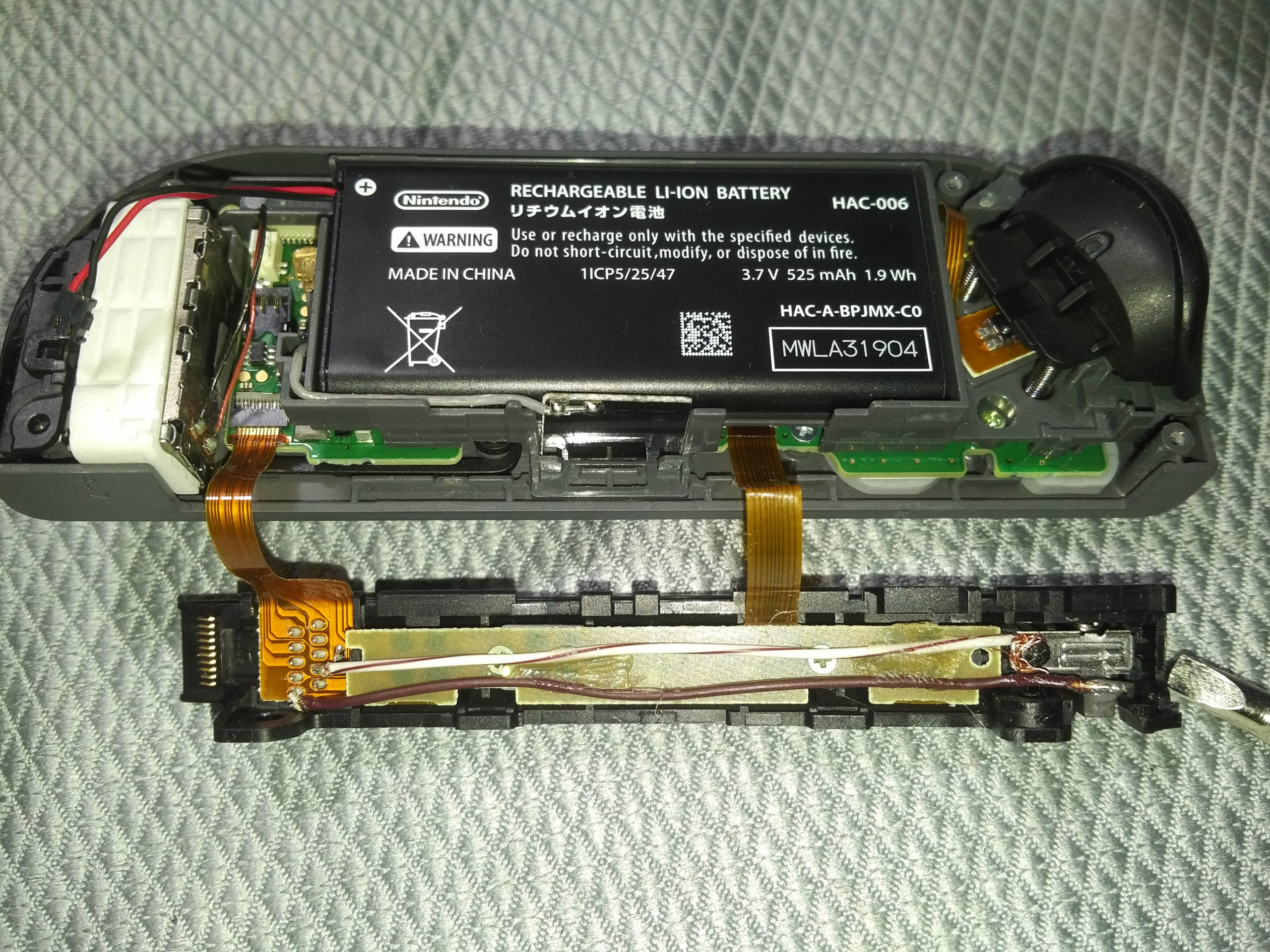
Step 4. Re-assemble LED PCB to rear cover rail, and hot glue both wires to the back of it
Replace the SR, SL, and Bluetooth sync buttons (make sure not to mix them up), and screw back in the LED PCB. Hot glue the two strands of wire to the back of this PCB running along the length towards SR.
Make sure to flatten your hot glue blobs, otherwise you’ll have difficulty in reassembly of the Joycon. These blobs help us secure the wires for the next operation – building our switch.
(graphic in last step)
Step 5. Strip 1cm (1/2″) of Pin #7 wire from the black release switch screw – strip and trim the rest off then wrap the stripped end around the black screw
To make this switchable, we’ll leverage the Joycon release button and make it electronically functional. The 1cm (1/2″) of stripped wire extending past the black screw is to be wrapped tightly around it (helps to unscrew it slightly first). The screw and silver piece of metal are conductive, and will serve as the static part of our switch.
(graphic in last step)
Step 6. Measure wire from Pin #10 to the end of the gray Joycon release wire – trim the rest off, strip 2mm (1/16″), and solder a flat blob no thicker than 1mm (1/32″) to the end
Measure the remaining Pin #10 length all the way to the gray Joycon release lever and cut off the excess. Strip 2mm (1/16″) of wire off this end for some solder. We’ll be making a 5mm (3/16″) wide circle, 1mm (1/32″) thick of solder at the end. Solder’s pretty soft, so you can get away with adding the solder, then flattening with a plyers.
Step 7. Secure solder pad to face of Joycon release lever moving inwards using epoxy
Attach this solder pad to the face of the lever actuating inwards (the lever moves in/out of the Joycon) using epoxy. Care should be taken that epoxy does not leak (hence, use a toothpick to apply), and is ONLY contacting the surface of the lever moving inwards, and not the arm of the lever moving behind the small silver metal plate.
When the lever is fully actuated (pressed inwards), the solder pad should contact the edge of the metal plate, completing our switch circuit and creating a short between pins #7 and #10. You’ve just built a de-facto normally-open (NO) switch!

Step 8. Test our NO switch – touch multi-meter probes to pins #7 and #10 while lifting and releasing the Joycon release switch lever
If your continuity test results in continuity when our lever is pressed inwards, and none when released, then our NO switch is complete and functional.
Step 9. Replace padding protecting rail pins, then reassemble Joycon
At this point we’re done modifying our right Joycon. We can begin reassembly by placing our little gray piece of foam back over the rail pins, trim any exposed wire and flatten connections/hot glue to keep the entire unit compact. Due to the gauge of chosen wire, your reassembly may be a little tough. Squeeze the two halves together like a sandwich, and use a rubber-band if needed to keep the unit together long enough to screw back in the back cover.
How to use
Whenever you have a Nintendo Switch unit that needs to enter RCM, attach the right Joycon to the unit, and power the unit down.
Hold the RIGHT JOYCON release button, Volume UP, and Power at the same time for 1 second, then release.
If nothing happens visually, then your switch is in RCM mode, and you can proceed with injecting whatever fun payloads you have in mind over USB-C 🙂
Next steps and thanks
Big thanks to the following communities and projects for making this possible.
- Katherine Temkin (@ktemkin) for disclosing the Fusée Gelée vulnerability in impeccable detail
- @ktemkin and Mikaela Szekely (@Qyriad) for fusee-launcher payload injector
- The Nintendo Homebrew crew and their fantastic Switch Guide in cooperation with the Atmosphère team.
- pbanj#9188 from the Nintendo Homebrew Discord for bringing this cool modification to light