Designing multi-part assemblies, you expect a certain amount of assembly AND disassembly.
When the material is from a FDM printer like PLA, assembly and disassembly can weaken and eventually break parts, very common with hinges, clips, and matted faces where you use fasteners like screws to secure two or more parts together.
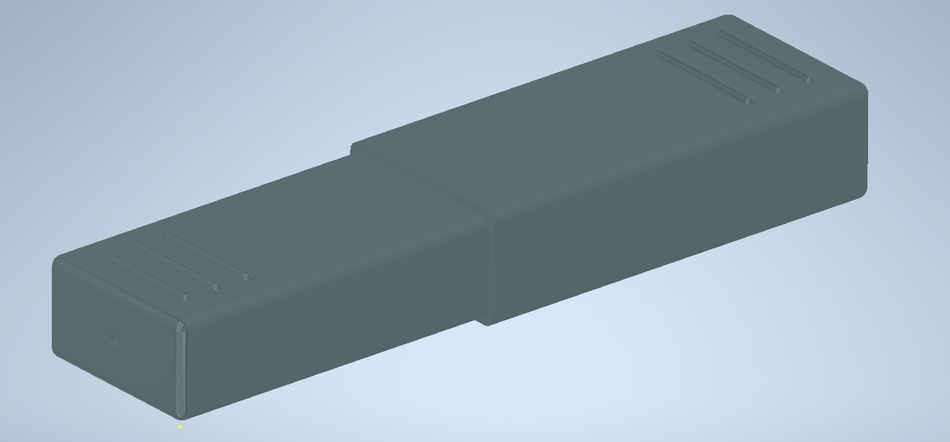
As part of a shooting gallery build I’m working on, there’s some design work needed for the target housing which contains both the target at rest, along with other components (motors, rack and pinions, lighting, micro switches). Other than the exposed target face, all other components will be contained within a box to keep them safe – however should one of these components fail like a stripped gear or stuck switch, I want the entire back to come off.

In terms of choice of inserts, I’ve went with INCLY 440PCS Threaded Inserts M2 M2.5 M3 M4 M5 M6 Brass Heat Set Inserts for Plastic Parts Metric Knurled Nuts Assortment Kit for 3D Printing Components Injection Molding – they seemed the most affordable at the time.
What’s nice is they have a size chart that breaks down the dimension of each insert:

I’m planning to use M3’s for the back cover attachment to the housing frame.
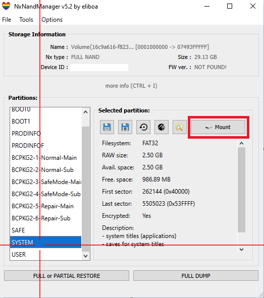
Now comes the question – how big should I make the hole for the insert?
I’m planning to use a soldering iron – put it on the tip, heat it up, then push it gently into the part.
However, too small a hole and it will deform the part. Too large a hole and the knurling will have nothing to grab onto, making a weak insert that eventually rounds the plastic or just falls out.
When using PLA, it’s important to note that any kind of hole tends to be 0.1 – 0.2 mm smaller as the plastic shrinks when it cools.
If you’re using ABS or Nylon those tend to shrink significantly more. Filament makers also don’t provide a ‘shrinkage coefficient’ that you can use to calculate this.
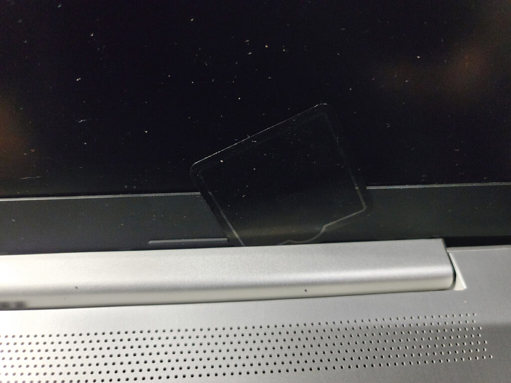
For the material I have on hand, one of the first prints tends to be a 1cm3 cube, I then use a caliper to measure how much shrinkage there is (typically for each cardinal direction X/Y/Z, then average).
Using this average shrink coefficient along with the smallest diameter of a M3 insert as seen in the chart above, I’ll size my holes 3.8mm exactly – this accounts for the above shrinkage where it matters most, at the knurling.

Construction lines show the difference in size, I don’t consider whatever material that will be displaced from the ~0.4-0.5mm to be significant (after factoring how much will fill the knurling grooves), excess I’ll just sand away. At the end of the day these are functional parts not models so they don’t need to be super pretty.