Creating a health dashboard by hacking intelligence into an AOpen (the ‘A’ for ancient) monitor; with metrics aggregated by Graphite and beautifully displayed with Grafana.
When it comes to hardware, I’ll be keeping things simple.
With the exception of the monitor itself, the other complex subsystems are as follows:
- Raspberry Pi Zero
- USB to USB/Ethernet hub
The remaining components are internal wires/cables, which includes the Mini HDMI to VGA adapter, and 5V/1A wall adapter.
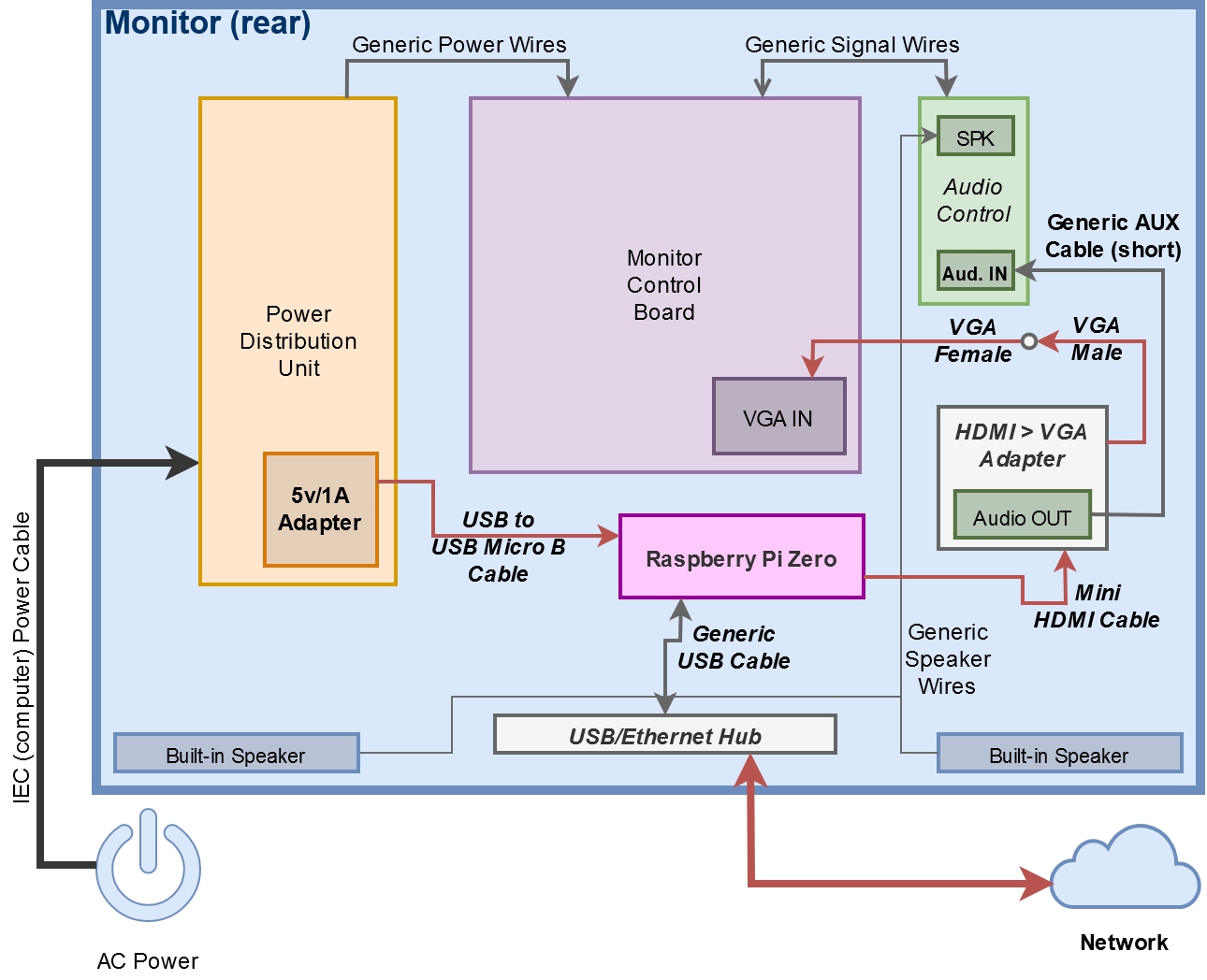
Internal Component/Wiring Diagram
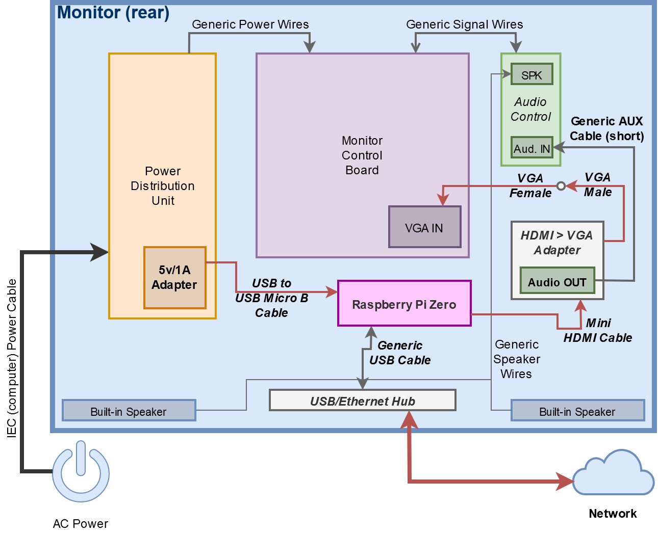
Legend for above diagram:
– Bolded titles are components ADDED to the vanilla monitor system.
– Italicized titles are components which had to be modified in some way.
– Red lines are cables which had to be modified in some way.
Component boxes nested within other component boxes are either mounted, or exist, on that component.
Let’s talk modifications
Certain cable/component modifications were pretty simple. For instance, the Mini HDMI Cable was folded at one end and held as such via some electrical tape. Other simple modifications included the Generic USB Cable used between the USB/Ethernet Hub and Pi Zero, and the Generic AUX Cable – both of which were looped and tied.
The rest were a little more complex; take the 5V/1A wall adapter for instance.
I didn’t bother hacking it open because the case played a valuable role in its mounting point.
Therefore to supply AC, I split the input from the Power Distribution Unit to both the unit itself and the 5V/1A wall adapter, connecting directly to the non-polarized plugs and wrapping the connection in shrink wrap.
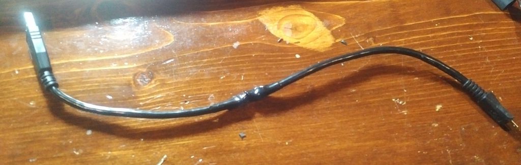
The USB to USB Micro B cable was drastically shortened to 30cm, and rejoined via small solder joint, and shrink wrapped.
The HDMI to VGA adapter was stripped of its hideously large housing and plugged into the monitor’s VGA cable.
At this point, wiring video would be complete in a traditional monitor. However, this monitor has its VGA cable BUILT-IN. Man, was this an annoying realization.
Fortunately, the other end wasn’t soldered onto the main board, and was rather some rather delicate AOpen proprietary connector.
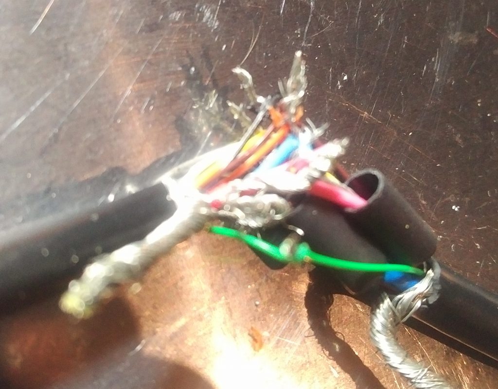
To ensure the integrity of this connector, I ended up splitting and shortening the built-in VGA cable to 30cm as well.
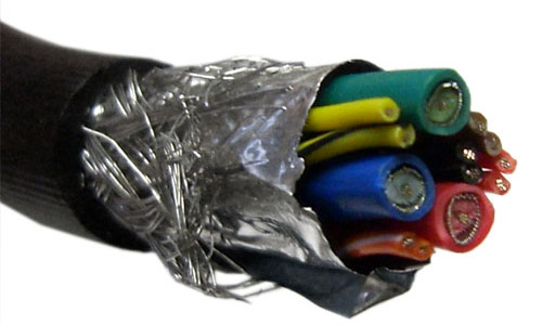
If you’ve ever wondered how all those pins in a VGA interface are sent along a single cable, I highly suggest you split a cable open to learn how.
It’s an absolute beast of a cable, this particular one having a woven metal sheathe surrounding 3 coaxial-like cables and 9 wires.
Soldering individual strands was challenging enough with the variety of stranded conductors. Keeping stripped conductors from contacting was a whole new bag of worms.
Hot glue came in useful for once, and helped not only hold the splice together, but keep each individual wire in place, preventing contact.
Cables connected, fingers crossed, let’s power it on
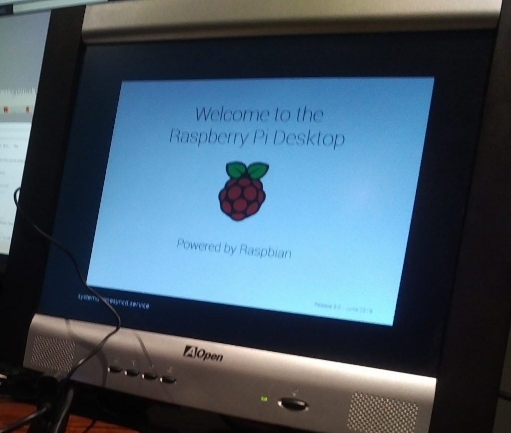
IT’S ALIVE!
Thank the stars that this picture excludes the mess behind the monitor 😉
This covers all the core system components.
We’ll be wrapping up on hardware soon – man, I can’t wait to put the rear cover back on.
We still need to talk about the USB/Ethernet Hub, and the Audio Control (both of which requiring some modifications), but we’ll leave that to the 4th GraPi post.