Creating a health dashboard by hacking intelligence into an AOpen (the ‘A’ for ancient) monitor; with metrics aggregated by Graphite and beautifully displayed with Grafana.
As promised, let’s dive into some of the modifications made to Audio Control and USB/Ethernet Hub – all part of the master plan.
Audio Control – Moving Audio IN, INside
With our cheap little Mini HDMI to VGA adapter providing audio output from the Pi, all we need to do is feed it into the monitor. Spoon of choice? AUX cable.
Now here’s where it gets a little awkward.
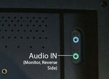
With
the unit closed, Audio IN is facing outwards. Meaning we’d have to lead
an AUX outside the unit and plug it into the back, making this odd
protrusion.
Well, that won’t do.
One of the key tenets of this project was to ensure the unit is compact, with as many components encapsulated within the monitor chassis itself.
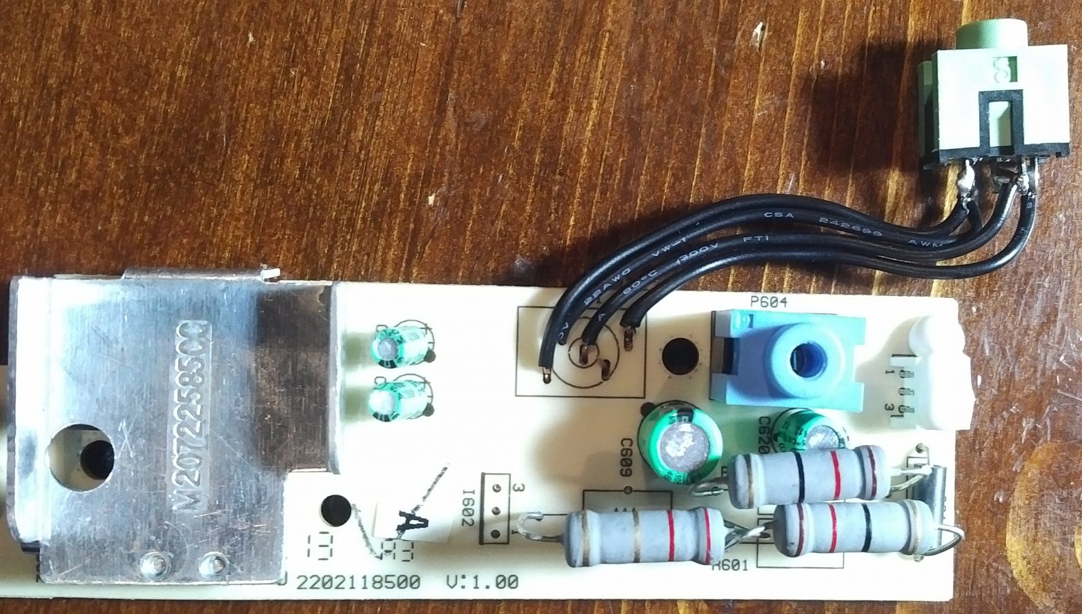
Let’s perform a surgery, and extract the Audio IN (AUX) port and see if we can move it around.

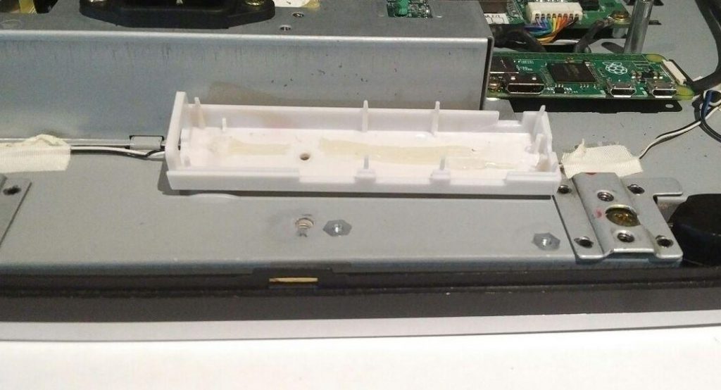
Audio Control board extracted; Audio IN looks pretty isolated, shouldn’t be too difficult to remove the connector from the PCB 
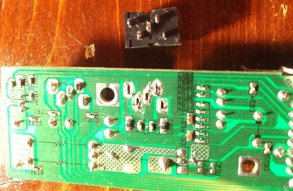
Audio IN AUX port extracted, desoldered joints on reverse side of PCB 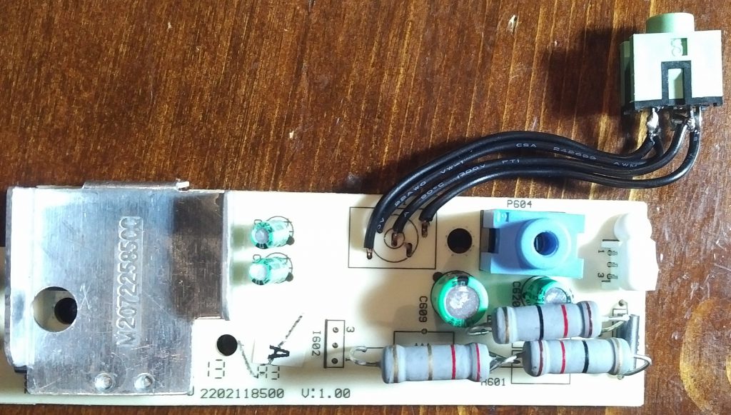
Added some simple single-conductor wire between the board and Audio IN AUX port so we can change its orientation inwards


And done. Time to test.
Powered on the unit, ensured the AUX cable was connected between our Mini HDMI > VGA adapter and Audio IN on the monitor, and basked in the graininess of Do You Remember remixed by grey.
Yeah, it was pretty bad.
Not because of the mod I assure you (having tested audio on this monitor awhile back), more so because the speakers are terrible.
Anyways, won’t be playing music through this anytime soon – any audio coming through the Pi will be for notifications/alarms.
USB/Ethernet Hub – Mounting
Never thought I’d say it, but for once, this modification was made EASIER by the cheap construction of a part.
The Ethernet/Hub adapter easily came apart (surprise), separating away from its case, allowing me to determine a suitable mounting location.
Deciding to mount it near the bottom for both out-of-sight accessibility came with the added bonus of being closer to the Pi.
To mount the hub, I ran one of the leftover hinge screws through the lower-half of the plastic hub case, right back into the frame.
All that was left was to cut a portion of the rear cover out to accommodate the area now taken by the hub, and we were good to go.

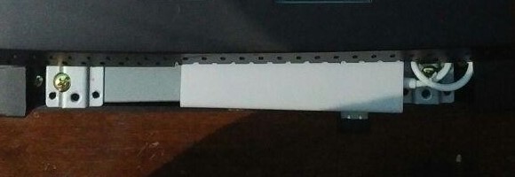
Lower-half of hub case flushed right against hinge, hole drilled to take advantage of existing threaded hole from the hinge that used to be 
Lower half screwed in, hub components and top case half reassembled 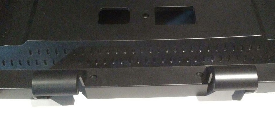
Lower part of the rear cover – originally intended to contain hinge construction, needs to go 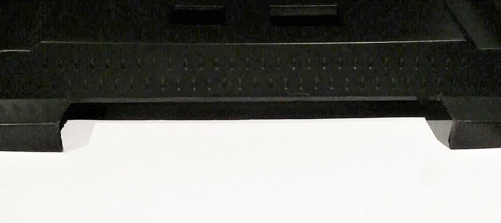
Some hacksawing and filing later, we’ve got a notch just for the hub, with enough clearance on the left for ethernet access 
Rear cover assembled! Realized at this point that the hub had a little wiggle room – eventually resolved by adding a screw to the right side


And there we go!
This wraps up a majority of the hardware.
For now.
The next post will cover assembly in more detail, along with any issues we should consider before side-mounting onto my server rack.