Electronics Theory
As part of electronic theory, we discussed what is electricity, the difference between digital and analog, and the components of a basic circuit. We also discussed a few examples of these, such as:
– Analog Devices – Clocks, Analog Televisions.
– Digital Devices – Calculators, Computers, Cameras.
– Components of a basic circuit – Loads, Power Sources, Conductors.
We also discussed the significance of Analog vs. Digital devices, where as analog devices can be interacted easier with the user, and where digital devices can store/calculate interpreted data. However, this data is stored in binary (1’s and 0’s).
Binary Numbers
Computer language compromising of 1’s and 0’s only (base 2 system). This is “computer language”, where as a 1 represents High, and 0 represents Low. Technically, a group compromising of true and false, that relay information. Binary can be calculated and converted from one system (binary = base 2 system) to another system (decimal = base 10 system).
This is significant to computer language, as thousands of bits can be computed in a mere millisecond. This is however, not resourceful for human/user use. As such, binary is often converted into analog signals that can be viewed and interacted by users.
Logic Gates
Logic Gates are compromised of electrical components (e.g. switches), that transform inputs into a designated output. They are often in chips, and each chip compromises of more than one gate.There are many gates, for example;
AND Gates, that only give a High output if both inputs are High.
Logic Gates are the “elementary” building blocks of electronic circuits. They also implement a Boolean function.
I personally play a sandbox game known as Minecraft. Within that game, there is an aspect of transferring information and energy. That aspect within the game is known as Redstoning. It is from playing minecraft, and redstoning, that I found out and played with the basics of Logic Gates to make simple tasks possible.
Circuit Project: Logic Probe
A logic probe is a device that can test the signal passing through a specific area of a circuit, and display a High or Low indicator (usually an LED). This device is significant for troubleshooting a circuit, and determining if electricity is not reaching a certain point, or if there is a short-circuit.
A Hobbyist’s essential when it comes to circuitry.
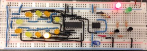
Circuit Project: LED Flasher Circuit
This lab involves the usage of a Timer555 chip to control an array of LEDs (make them flash).
This lab also involves the usage of a capacitor that controls the flash rate frequency.
This lab was a test of our knowledge in the flow of electricity, the usage of the Timer555 chip, and our overall electronic circuitry skills.
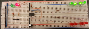
Circuit Project: Roulette Wheel
Similar to the flashing color wheel seen at casinos, this project was to create a wheel of LEDs that flashed on and off in sequence. To make this possible, the previous project of a timer circuit was used in conjunction with a 4017 decade counter. This chip took the pulses from the timer to sequence through a series of outputs. From this point, all that had to be done was connect each LED to a corresponding output pin on the counter.
The counter segment wiring took the most time and patience, for there were 10 LEDs, each with two wires running out of it (one from counter to positive, then from negative to ground). This made the small breadboard more cramped than it was already. However, it managed to be functional in the end.
One revision that I would’ve made would be to the flash rate. A higher flash rate would have looked better. To accomplish this, I could swap out R2 (or the 320k OHM) resistance for a lower ohm resistance.
Circuit Project: Network Cable Tester
As my final project, I have decided to create an Ethernet Cable Tester. This device will be a simple continuity tester that will take the two ends of an RJ45 cable, and sent a pulse through. The initial pulse and the received pulse will be aligned alongside each other, as such; you will be able to tell whether the cable is a crossover, straight-through, etc. The circuit will have a potentiometer, which allows the user to determine the pulse rate. All of this will be within a plastic case (still to be determined), with either a 1.5v AA battery, or a 9v (to be determined). LED-wise, will either use a set of red & blue, or red & green – one length for signal sent, and signal received.
I chose to create a cable tester, for it is directly associated with my career of becoming a Network Administrator. Even though I am not wiring entire workspaces, I’m currently working on a personal network project at home, and a cable tester would prove very helpful.